
In architecture, a section is a reading tool of the building that shows what no horizontal plan can reveal: the ceiling height, the thickness of a floor, the layout of a staircase, or the slope of a roof. Two types of sections dominate professional practice, the longitudinal and the transverse, and their distinction is based on the orientation of the cutting plane relative to the main axis of the structure.
Understanding this distinction is crucial for correctly reading a building permit application or a design project.
Architectural section and thermal regulations: what RE2020 has changed
The available content on the subject focuses on the geometry of sections or their administrative role in an urban planning file. They overlook a recent change that concretely modifies the content of these documents: the evolution of requirements related to RE2020.
Since the implementation of this regulation, construction choices in new housing have profoundly changed. The generalization of heat pumps, the decline of gas, and the electrification of uses require these systems to be included in the sections. A decree from December 2024 related to RE2020 has further strengthened these obligations for designers, who must now translate environmental constraints into their technical documents.
Specifically, a longitudinal section shows the distribution of energy systems along the length of the building: ventilation network, ducts, technical rooms. The transverse section, on the other hand, is more useful for checking the thickness of the insulating envelope and identifying thermal bridges at the level of floors or wall-to-roof connections. The differences between longitudinal and transverse sections in architecture are therefore no longer just a matter of geometry, but also of energy compliance.
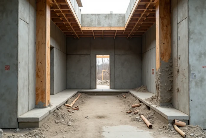
Longitudinal section plan: orientation and visible information
The longitudinal section slices through the building in the direction of its greatest dimension. For a rectangular house, the cutting plane runs parallel to the longest façade. This choice of orientation allows for visualizing the sequence of rooms along the main axis, the level variations between different spaces, and the relationship between the ground floor and the upper floors throughout the depth of the construction.
This type of section is particularly useful for elongated buildings (multi-family housing, public facilities, industrial warehouses). It highlights:
- The profile of the natural terrain along the entire length of the plot, allowing for verification of the building’s placement relative to the contour lines
- The layout of horizontal networks (ventilation, heating, drainage) that run under the floors or in the false ceilings
- The height relationships between different interior volumes, including double heights or mezzanines
The longitudinal section follows the main networks and technical rooms along the length of the building. This is why designers prefer it when they need to demonstrate the feasibility of duct passage or the compliance of an air network.
Transverse section in technical drawing: what it reveals differently
The transverse section slices through the building perpendicular to its main axis, that is, in the direction of its smallest dimension. It reveals a thin slice of the building, as if one were cutting a loaf of bread and looking at the crumb.
This orientation highlights information that the longitudinal section does not show, or shows poorly. The load-bearing structure (party walls, columns, beams) appears in its logic of vertical load transfer. The thickness of the envelope and thermal bridges are readable on the transverse section, making it a reference document for thermal engineering offices.
It also makes visible the roof slope, the ridge height relative to the natural terrain, and the offset between the finished interior level and the exterior ground. In a building permit application, the transverse section is often the one that allows the reviewer to verify compliance with the maximum heights set by the local urban planning plan.
Choice of cutting plan: a technical decision, not arbitrary
The layout of the cutting plan on the current floor plan follows a precise logic. The architect chooses an axis that passes through the most significant elements of the project: a staircase, a void over the living room, an elevator shaft. The section must “tell” as much information as possible in a single drawing.
A poorly placed cutting plan can obscure a problem of height under a beam or a conflict between a network and a structural element. The choice of cutting plane conditions the readability of the project, and the same building may require several sections in each direction to cover all critical situations.
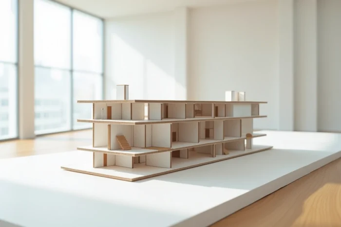
Section and construction plan: why not to confuse the two
The confusion between plan and section remains common, even among professionals at the beginning of their careers. Conceptually, plan and section use the same principle of orthogonal projection. The difference lies in the orientation of the cutting plane: horizontal for the plan, vertical for the section.
The plan shows the distribution of rooms at a given level, viewed from above. The section shows the superposition of levels, viewed from the front. The two documents are complementary and should be read together. A plan without a section does not convey anything about the height of the spaces. A section without a plan does not allow for locating the exact position of the cutting line.
The façade, a third type of representation often associated, is distinguished from the previous two by a fundamental point: it only shows the exterior of the building. No information about the internal structure, networks, or wall thicknesses is included. The façade is a projection, the section is a section. This distinction may seem elementary, but it conditions the proper reading of an architectural file.
Contemporary practice, driven by the generalization of BIM software, has made the generation of sections almost automatic from the digital model. The available data do not allow for concluding that this automation eliminates the need to know how to read and interpret these documents. Knowing how to distinguish a longitudinal section from a transverse one remains a prerequisite for any building professional, whether they are using a pencil or a modeling software.